


Products
Search

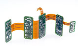
 Rigid-flex printed circuits
1. Introduction
Rigid-flex printed circuit boards means hybrid systems, which combine the characteristics of rigid and flexible circuit substrates in one product. Whether in medical technology, sensors, mechatronics or in instrumentation, electronics squeezes ever more intelligence into ever smaller spaces, and the packing density increases to record levels again & again. Using flexible PCBs and rigid-flex printed circuit boards, whole new horizons open up for electronic engineers and designers.
- Reduction of weight and volume
- Defined characteristics of the circuit systems on the circuit board (impedances and resistances)
- Reliability of the electrical connections due to reliable orientation and reliable contacts as well as savings on connectors and wiring
- Dynamically and mechanically robust
- Freedom to design in 3 dimensions
2. Materials
Apart from the thickness of the polyimide, the materials mainly differ in their adhesive systems (glueless or on epoxy or acrylic basis) as well as in the copper quality. For comparatively static bending applications with a low number of bend cycles (for assembly or maintenance) ED (electro-deposited) material is adequate. For more dynamic, flexible applications RA (rolled annealed) materials must be used.
Materials are selected on the basis of the product and production specific requirements, and the datasheets of the materials used can be requested as required.
Adhesive systems: As a bonding agent between the flexible and the rigid materials, systems using adhesive on an epoxy or acrylic basis (which is still capable of reacting) are used. The options are as follows:
- Composite film (polyimide film coated on both sides with adhesive)
- Adhesive films (adhesive systems poured onto a paper base and covered with a protective film)
- No-flow prepregs (glass mat/epoxy resin prepreg with very low resin flow)
3. The characteristics of flexible materials
Flexible materials differ from rigid materials in their essential characteristics, which have to be taken into account:
- Significant reduction of copper adhesion at higher temperatures (e.g. when soldering)
- Increased water absorption
- Changes of dimensions which are larger, by a factor of up to 10 in the individual production stages, especially for wet processes
4. Layout guidelines
From the differences mentioned above, for the layout and use of rigid-flex printed circuits, the following can be deduced:
- For single-sided flexible circuits, the bending radius is approximately 6 x the thickness
of the flexible material, and for double-sided circuits it is approx. 12 x the thickness. - Choose track widths and spacing in the flexible region to be as large as possible (> 150 µm)
- The flexible region should have parallel tracks which are the same width, with the same leakage resistance, and which run at 90° to the bend line
- Tracks should extend at least 1 mm into the rigid region
- On flexible layers, include hatched copper areas which are as large as possible
- The tracks on double-sided, flexible parts should be symmetrically offset
- Holes should be at least 2 mm away from a flexible part
- Choose solder surfaces to be as large as possible, the diameter of solder eye pads should be at least twice the diameter of the hole.
- Solder must not come closer than 1 mm to the flexible area
- Add about 1 mm all round to the dimensions of openings in non photostructured covering films
- To be able to assemble the components on a board, to solder & check them, a stiff frame with defined breaking points should be used. Blanks can contain single or multiple boards.
- Always use smooth (round) milling transitions to the connected parts of the circuit
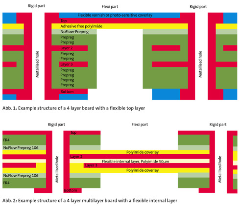
5. Assembly variations
CONTAG manufactures rigid-flex printed circuit boards with flexible external or internal layers.
6. Processing notes
In principle rigid-flex printed circuits can be soldered without restrictions using the parameters for rigid printed circuits.
As polyimide film is however very hygroscopic, it is vital to dry the item before soldering. If this is not done, delamination may occur, bubbles may form or sleeves may rip out during the soldering process.
We recommend drying for > 4 h at 120°C and then processing immediately (< 8 h) afterwards.
When designing rigid-flex printed circuits, there are many possible options for the construction and for the materials used.
Talk to our sales team (+49 30 351 788 - 0 or team
 contag.de). We will look together for a functional, optimised and cost-effective solution for your printed circuit boards.
For more detailed technological questions on printed circuit boards, please contact our team of technologists (+49 30 351 788 - 155).
Version: E
Your personal contact
+49 30 351 788-333
teamcontag.de
 Rigid-flex printed circuits product info