


Products
Search

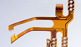
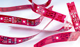
 Flexible printed circuits
1. Introduction
Flexible printed circuits have become established in recent years as a medium for circuits.
The main users of flexible printed circuits are the technological sectors which need the following characteristics and benefits:
- Implementation of compact, complex assemblies which minimise size and weight
- Dynamically and mechanically robust when bent
- Defined characteristics of the circuit systems on the circuit board (impedances and resistances)
- Reliability of the electrical connections by minimising the number of connections between the modules
- Saving connectors and wiring, also cost-saving by lowering the costs for component placement and assembly
Flexible base material: As a base material, CONTAG uses exclusively polyimide film which, compared to the alternative PET and PEN films has the advantage of a high processing temperature range, unrestricted solderability as well as the large operating temperature range. Depending on the requirements for the product and process, differing versions of film are used.
| Characteristic | Version | Description |
|---|---|---|
| Polyimide thickness | 25 µm, 50 µm, 100 µm | CONTAG standard: 50 µm |
| Copper | Single or double sided | |
| 18 µm, 35 µm, 70 µm | CONTAG standard: 18 µm or 35 µm | |
| Rolled copper (RA) | Suitable for dynamic, flexible applications | |
| Electrolytically deposited copper (ED) | Low elongation after fracture, only suited for static and semi-dynamic applications | |
| Adhesive systems | Acrylic adhesive | For dynamical, flexible applications, not UL 94 V-0 listed |
| Expoy adhesive | Limited dynamic flexibility, UL 94 V-0 listed | |
| Adhesive free | CONTAG standard, high flexibility, chemical resistance, and is UL 94 V-0 listed |
Flexible protective films:
| Type | Version | Description |
|---|---|---|
| Polyimide Coverlay | Polyimide thickness: 25 µm or 50 µm, acrylic or epoxy adhesive, thickness of adhesive: 25 µm or 50 µm | Is pressed on, solder pad holes must first be drilled, milled or laser cut |
| Photo-sensitive Coverlay | Thickness: 63.5 µm | Is laminated on and then exposed and developed like solder resist |
| Flexible solder resist | Elpemer SD2463-SM | Is applied using a silk-screen process |
3. The characteristics of polyimide films
The essential characteristics of flexible materials differ from rigid materials. To guarantee the best layout of flexible printed circuits, some fundamental characteristics of flexible polyimide materials must be understood:
- Significant reduction of copper adhesion at higher temperatures (e.g. when soldering)
- Increased water absorption (by a factor of 6 compared to FR4)
- Changes of dimensions which are larger, by a factor of up to 10 in the individual production stages, especially for wet processes (higher manufacturing tolerances necessary).
The following table shows a few typical values of a glueless flexible laminate used by CONTAG.
We will of course send you detailed datasheets of the material used, on request.
| Characteristic | Typical value |
|---|---|
| Dielectric constant at 1 MHz | 3,2 |
| Dielectric strength (V/µm) | 275 |
| Leakage resistance (Ohm) | 2.0 x 10,000,000 |
| Resistivity (Ohmxcm) | 5.0 x 100,000,000 |
| Cu adhesion (N/cm) | 10 |
| Shrinkage after etching (%) | 0,05 |
| Shrinkage after drying (%) | 0,05 |
| Max. operating temperature (°C) | 200 |
| Withstand solder bath (°C) | 400 (1 min) |
| Water absorption (%) | <1,5 |
| Expansion (ppm) | <60 |
| UL rating | UL94VTM-0 |
4. Layout guidelines
From the differences mentioned above, for the layout and use of flexible printed circuits, the following can be deduced:
- For single-sided flexible circuits, the bending radius is approximately 6 x the thickness of the flexible material, and for double-sided circuits it is approx. 12 x the thickness.
- Choose track widths and spacing in the flexible region to be as large as possible
- The bendable region should have parallel tracks which are the same width, with the same leakage resistance, and which run at 90° to the bend line.
- The transition from wide to narrow tracks should not be abrupt, but should gradually taper
- The transition from wide to narrow tracks at a 90° angle should use curves with as large a radius as possible
- If possible include large, hatched Cu surfaces in the layout.
- The tracks on double-sided, flexible parts should be symmetrically offset
- Choose solder surfaces to be as large as possible, the diameter of solder eye pads should be at least twice the diameter of the hole.
- The connections between tracks and solder eyes should be tear-shaped and rounded
- Add about 1 mm all round to the dimensions of openings in non photostructured covering films
- Always use smooth (round) milling transitions
- At the place where flexible extensions are supposed to bend, add additional copper tracking to prevent tearing.
- Selective mechanical reinforcements in the area of connectors or components is possible with film (thickness 100 µm - 150 µm), or with FR4 material (any thickness)
5. Processing guidelines
- Owing to the high water absorption shown by polyimide, flexible printed circuits must be dried before placing components and soldering (2 h at 120°C), and must then be processed within 6 h.
- The solder parameters for rigid printed circuit boards can be used
6. The manufacture of flexible printed circuit boards at CONTAG
CONTAG currently makes samples and small series of single and double-sided, flexible circuits. The standard surface finish is electroless tin. Depending on the requirements, quantity and layout, contours are preferably cut by laser, but mechanical milling is also possible.
When producing the design and layout of flexible circuits, you should contact us during the planning phase to discuss the selection of material and design, so that we can work together to produce the ideal solution.
Talk to our sales team (+49 30 351 788 - 0 or team
 contag.de). We will look together for a functional, optimised and cost-effective solution for your printed circuit boards.
For more detailed technological questions on printed circuit boards, please contact our team of technologists (+49 30 351 788 - 155).
Version: F
Your personal contact
+49 30 351 788-333
teamcontag.de
 Flexible printed circuits product info